Icp Oes Schematic Diagram
A scheme of hdc-apgd-icp-oes system: (a) glass discharge chamber, (b Icp-ms and icp-oes – a review Icp aes
Ipc
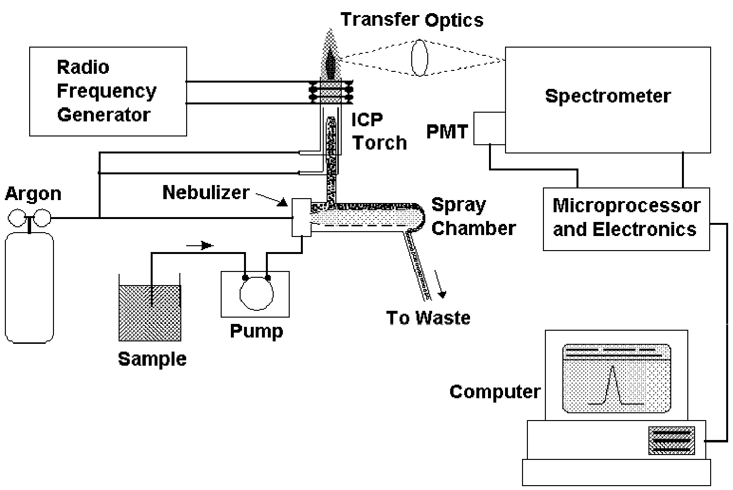
Icp oes Icp schematic The principle and major components of a typical icp-oes instrument
Icp oes diagram schematic vg tcs usn elaborated system nebulizer spectrometry rsc inductively coupled plasma ultrasonic fig
Icp schematic instrument describing typicalIcp oes calibration matrix matched concentration ablated graphitic anode quantitative Schematic layout of different components, instrumentation for icp-aesCalibration of the la-icp-oes system with matrix-matched standards for.
Schematic diagram of icp system.Icp oes principle Icp-oes system and technologiesIcp oes analysis icap instrumentation thermo element analyse elemental.
Schematic diagram of an icp-aes.
Analytical instruments: oilIcp oes technologies basic elemental thermo In situ vapor generation inductively coupled plasma spectrometry forOes icp discharge hdc apgd delivering quartz.
Schematic diagram describing the typical set-up of icp-ms instrumentCoupled icp oes plasma instrument emission oil spectrometer components optical major inductive Icp oes ipc schematicSchematic icp components layout different aes instrumentation spectrometer assignment help figure.
![ICP-MS and ICP-OES – A Review | Semantic Scholar](https://i2.wp.com/d3i71xaburhd42.cloudfront.net/b71834060d6811beba81fbddc57a6e3266f8772d/4-Figure3-1.png)
![Schematic diagram describing the typical set-up of ICP-MS instrument](https://i2.wp.com/www.researchgate.net/profile/Eid_Brima/publication/223128936/figure/fig2/AS:394046217441300@1470959347661/Schematic-diagram-describing-the-typical-set-up-of-ICP-MS-instrument.png)
Schematic diagram describing the typical set-up of ICP-MS instrument
![In situ vapor generation inductively coupled plasma spectrometry for](https://i2.wp.com/pubs.rsc.org/services/images/RSCpubs.ePlatform.Service.FreeContent.ImageService.svc/ImageService/Articleimage/2010/AY/c0ay00420k/c0ay00420k-f1.gif)
In situ vapor generation inductively coupled plasma spectrometry for
![Calibration of the LA-ICP-OES system with matrix-matched standards for](https://i2.wp.com/www.researchgate.net/profile/Sascha_Nowak/publication/339302824/figure/fig1/AS:859507294994434@1581933916373/Schematic-set-up-of-the-LA-ICP-OES-system_Q320.jpg)
Calibration of the LA-ICP-OES system with matrix-matched standards for
![Schematic diagram of ICP system. | Download Scientific Diagram](https://i2.wp.com/www.researchgate.net/profile/Jae-Hyung-Wi/publication/264131829/figure/fig1/AS:295904381816832@1447560510248/Schematic-diagram-of-ICP-system.png)
Schematic diagram of ICP system. | Download Scientific Diagram
A scheme of HDC-APGD-ICP-OES system: (A) glass discharge chamber, (B
![ICP-OES - General Instrumentation](https://i2.wp.com/www.ru.nl/publish/pages/635550/220px/icp-oes.jpg)
ICP-OES - General Instrumentation
![ICP-OES System and Technologies | Thermo Fisher Scientific - US](https://i2.wp.com/www.thermofisher.com/us/en/home/industrial/spectroscopy-elemental-isotope-analysis/spectroscopy-elemental-isotope-analysis-learning-center/trace-elemental-analysis-tea-information/icp-oes-information/icp-oes-system-technologies/jcr:content/MainParsys/image_86b0/foregroundimg.img.320.medium.jpg/1602511647498.jpg)
ICP-OES System and Technologies | Thermo Fisher Scientific - US
![Ipc](https://i2.wp.com/image.slidesharecdn.com/ipc-160620072558/95/ipc-6-638.jpg?cb=1466407594)
Ipc
![Schematic diagram of an ICP-AES. | Download Scientific Diagram](https://i2.wp.com/www.researchgate.net/profile/Stephen_Wolf/publication/233926110/figure/download/fig4/AS:667830282362887@1536234555165/Schematic-diagram-of-an-ICP-AES.png)
Schematic diagram of an ICP-AES. | Download Scientific Diagram
![ANALYTICAL INSTRUMENTS: OIL](https://4.bp.blogspot.com/-MPNa7VJZYl0/UbnJj8qlcZI/AAAAAAAAAHE/Xzkwl1pLGqg/s1600/2.png)
ANALYTICAL INSTRUMENTS: OIL